 English
 عربى
عربى 简体中文
简体中文
Air Cooled Condenser Coil with Fan: What Actually Sets Performance
How to choose, install, and maintain the coil-and-fan package that sets your condensing pressure—and your energy bill—for years.
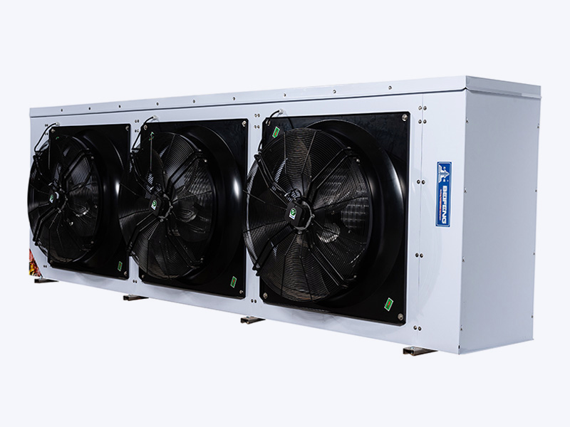
A cold storage contractor once ordered a replacement condenser coil using only face area and tube count as the selection criteria. The new coil fitted the existing condenser frame perfectly, yet the R-404A system began tripping on high discharge pressure every hot afternoon. The problem was not the coil itself; it was the fan. The new coil had a denser fin pitch and a higher air-side pressure drop, while the existing fan simply could not push the required airflow through it.
The lesson is straightforward: an air cooled condenser coil with fan behaves as one thermal system, not two independent components. If you specify one without the other, you will carry the consequences through the first summer.
The Coil Sets the Surface, the Fan Sets the Air
A bare finned coil in still air rejects only a fraction of the heat it handles with forced convection. The fan is not an accessory; it is what turns static surface into rated capacity. For a given coil geometry, heat rejection is roughly proportional to airflow up to a useful limit. A 10 percent drop in volumetric airflow can reduce heat rejection by 6 to 10 percent, pushing the condensing temperature up by several kelvin.
There are three effects to watch when matching a fan to a coil:
- Static pressure drop across the fin pack. Dense fins and multiple rows add resistance. A fan selected for free air will move far less air when installed against the coil.
- Air velocity distribution. If the fan creates a concentrated jet, parts of the coil see high velocity while other areas stay idle, causing uneven condensing and under-used surface.
- Fan energy and noise. Oversized fans waste electricity and force noise-control measures that could have been avoided with proper coil selection.
In practice, this means the coil and fan should be selected from the same performance curve, not from separate catalogue pages.
Key Specification Decisions
Start with the operating envelope, not the brochure. An air cooled condenser coil with fan must reject a defined heat load at a design ambient temperature, and it must keep doing so as dust, rain, and wind enter the picture.
For new projects, fill in the following fields before contacting a supplier:
| Parameter | What it influences | Common field trap |
|---|---|---|
| Total heat rejection at design ITD | Coil surface and fan air quantity | Using compressor motor power instead of heat rejection |
| Design dry-bulb ambient temperature | Condensing pressure at peak summer load | Averaging over the season instead of using local peak |
| Fin spacing / fins per inch | Air pressure drop, dust retention, frost behaviour | Choosing tight spacing to save material, then paying for cleaning |
| Face velocity | Airflow uniformity and sound level | Allowing face velocity above 3.5 m/s in noise-sensitive sites |
| Fan control strategy | Part-load power and condensing pressure stability | Running single-speed fans whenever the compressor runs |
If you prefer a formal calculation route, the condenser selection calculation guide walks through the basic steps and common references.
Corrosion protection is equally practical. Copper tubes with aluminium fins remain the most common construction, but coastal sites, industrial atmospheres, and food-processing areas often require an epoxy-coated fin block or heavier material. Decide from the actual environment, not from the price list alone.
Fan Control and Part-Load Efficiency
A fixed-speed fan sized for the hottest day will hurt your part-load economics for the rest of the year. Most refrigeration systems run below full capacity for more than 80 percent of their operating hours. If the condenser fan continues at full speed whenever the compressor runs, the condensing pressure drops in cold weather, causing low head pressure, poor refrigerant distribution, and wasted electrical energy.
For many industrial plant rooms, staging the condenser fans is the single most cost-effective energy improvement. The same condenser coil with properly staged fans can save more energy in a year by reducing fan power and stabilizing compressor conditions than a 10 percent larger coil would save by adding surface.
Modern options include multi-speed AC motors, two-step fan cycling, and EC fans with analogue speed control. EC fans are especially useful because they can hold condensing pressure close to the setpoint while drawing significantly less power at reduced load. In supermarkets and containerised refrigeration, this behaviour directly improves annual energy cost.
Success: Applying EC fans with 0–10 V control on an air cooled condenser can reduce fan energy by 20 to 40 percent compared with on-off cycling of single-speed fans, while keeping the head pressure within a tight band.
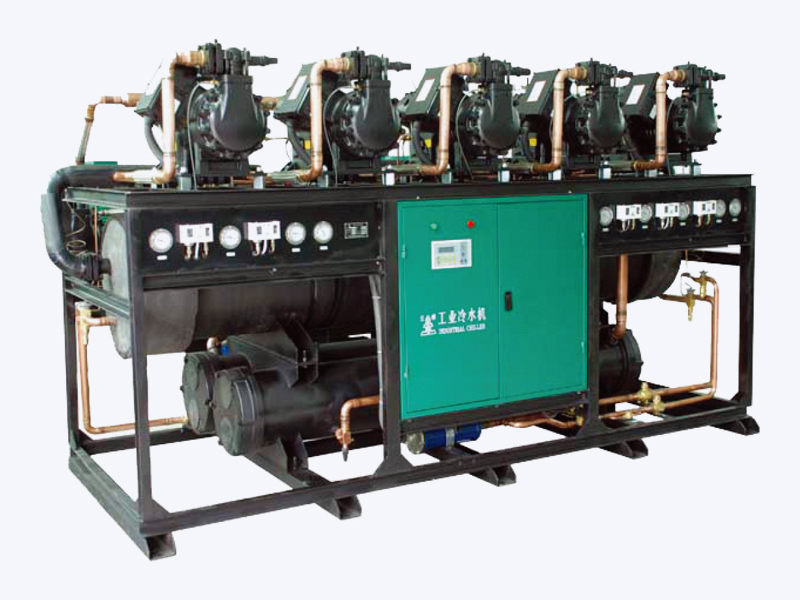
For higher-capacity projects, packaged screw-type condensing units already integrate multiple fans and control logic as part of the factory package.
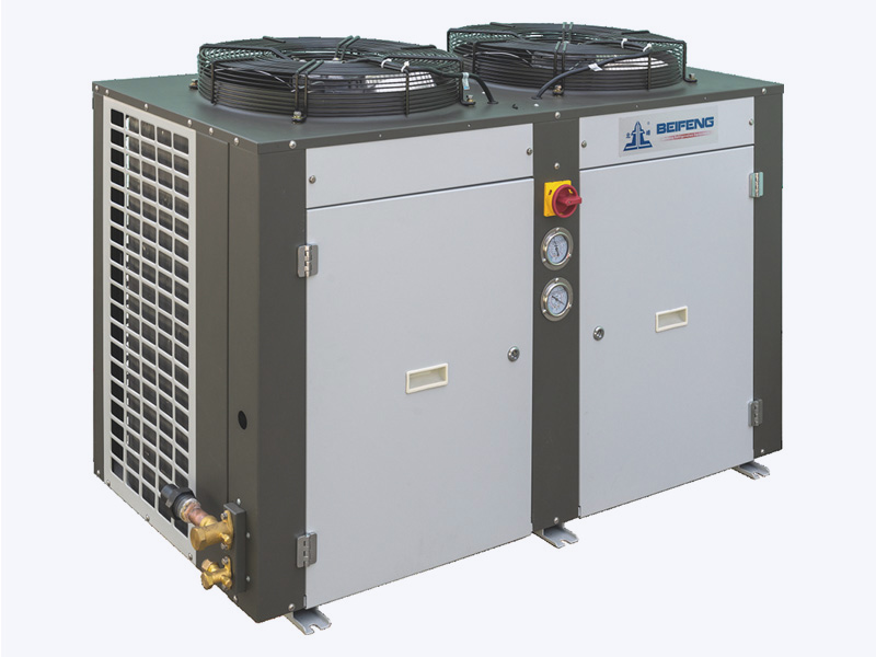
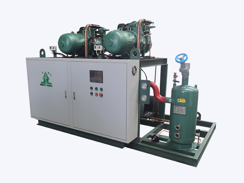 Screw-Type Condensing Unit for High-Capacity RefrigerationThis packaged screw condensing unit covers evaporating temperatures from 10°C to -40°C with optional economizers and multi-level energy adjustment. It is a factory-integrated solution worth reviewing for larger projects where proper placement and maintenance are critical.View Product →
Installation and Maintenance Realities
No coil and fan combination survives poor airflow management or dirty fins. The best selection is only a promise until the unit is placed and maintained correctly.
Hot air recirculation is the most common installation fault. Condenser fan discharge must have clear passage to the atmosphere, and the inlet side must not face the discharge of another condenser or a nearby wall. Recirculation raises the entering air temperature by several kelvin and reduces the effective temperature difference across the coil.
Warning: Do not mount an air cooled condenser coil with fan within 2 metres of a building fresh-air intake or a pressure-equalisation wall. Prevailing wind can push the warm discharge back into the inlet, causing high-pressure trips that lead to repeated service calls.
Dust, pollen, and industrial fibres collect on the fin surface. A thin, uniform layer reduces heat transfer far more than a modest reduction in air velocity. In dusty interiors, wider fin spacing is easier to clean; in coastal areas, corrosion protection must be checked during every service visit.
Info: Schedule cleaning based on the measured pressure drop across the coil, not only on a calendar. If the static pressure drop increases by 20 percent above the clean value, the fin pack needs attention.
Danger: A locked fan rotor, a failed contactor, or a loose belt can stop airflow without stopping the compressor. The condensing temperature will rise quickly. Always verify fan rotation and current on systems that have undergone replacement of the coil or fan.
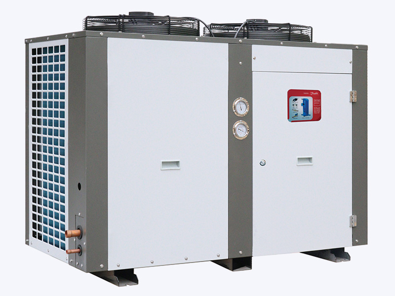
Noise-sensitive locations deserve a quiet fan selection from the start. A low-noise packaged unit with carefully chosen blade pitches and low motor speeds can avoid acoustic complaints that are almost impossible to solve later.
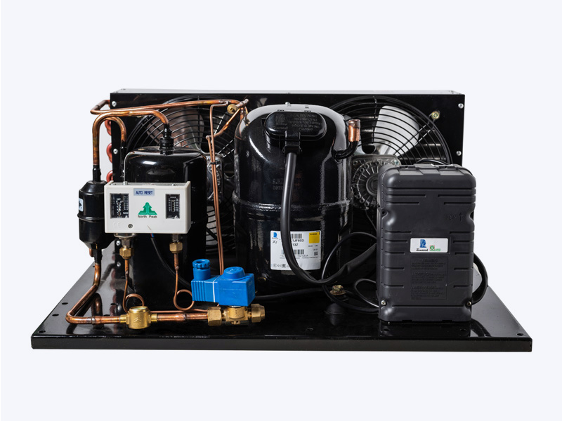
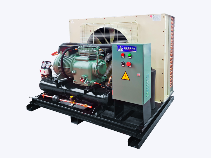 Low-Noise Semi-Hermetic Open-Type Condensing UnitThis commercial condensing unit features an open structure for easier maintenance, a silent axial fan with large blades, and a crankcase heater for reliable cold starts. It is a practical choice for noise-sensitive locations, offering complete packaged reliability.View Product →
Moving from Component to Complete Condensing Unit
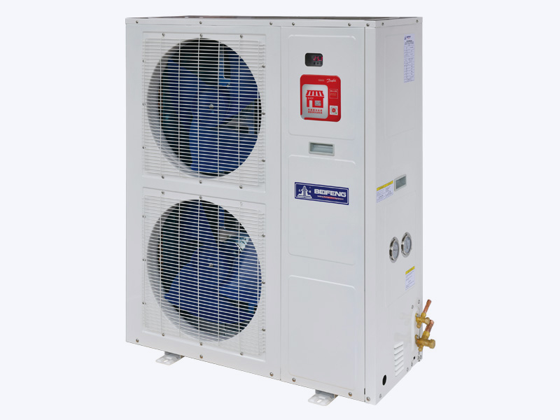
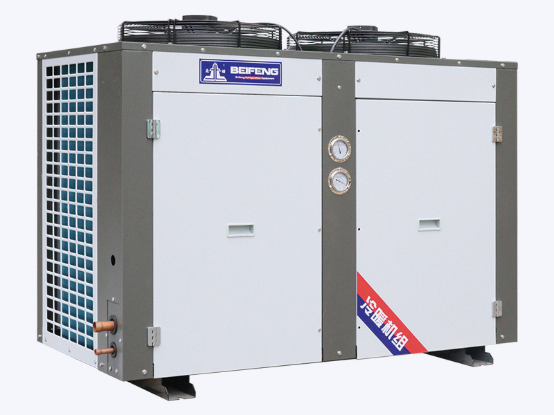
Ordering a loose air cooled condenser coil with fan is a reasonable path only if you have in-house engineering capacity to match it to a compressor, receiver, and controls. Most refrigeration contractors are better served by a complete condensing unit, where the coil, fan, compressor, and control panel are selected as a package.
- The fan curve is matched to the coil pressure drop at the factory.
- Refrigerant charge, oil return, and head pressure control are engineered together.
- Leak testing and run testing are completed before delivery.
- One manufacturer carries the responsibility for performance and warranty.
For example, semi-hermetic air-cooled condensing units pair a serviceable compressor with a condenser coil and axial fans on a common frame, which simplifies installation and troubleshooting.
Conclusion
An air cooled condenser coil with fan is not a commodity spare part; it is the heat rejection stage of the whole refrigeration system. The coil provides surface, the fan provides air, and the two must be engineered as one.
Start with the heat rejection duty and the real local ambient temperature. Decide fin pitch and corrosion protection from the environment. Plan fan control for the hours when the system runs below full load. Install the unit where air flows freely, and clean both fins and fans on a schedule driven by measurable performance loss.
For existing systems, measure the temperature difference across the coil and check the running current of every fan before suspecting refrigerant shortage. For new systems, avoid component roulette—use a factory-matched condensing unit and keep a record of the design assumptions. If the operating profile is unusual, send the details to your supplier before placing the order.
.jpg?imageView2/2/w/300/h/300/format/webp/q/75)