 English
 عربى
 简体中文

Air-Cooled Condenser Design Parameters: The Numbers That Decide Real Performance
A condenser sold as 100 kW at 35 °C and sea level will not deliver 100 kW at 43 °C and 1,600 m. Nothing has failed; three parameters have moved at once. Air density falls, the approach temperature widens, and the coil that looked adequate on paper becomes the bottleneck in July.
Five parameters decide most refrigeration and process cooling projects: design ambient dry-bulb temperature, approach temperature, airflow across the coil, refrigerant-side pressure drop, and part-load control. Fin spacing, fan arrangement and tube material exist to serve those five. What follows is the order in which they are worth checking.
Design Ambient Temperature Is Not Average Summer Weather
Design ambient is the dry-bulb temperature the coil must reject heat against at the worst credible hour, not the monthly average. Central and northern Europe commonly designs to 32–35 °C; the Middle East, North Africa and parts of the southern United States design to 43–46 °C. A unit selected at 35 °C and installed in a 45 °C climate runs a condensing temperature 8–10 K higher than intended, which raises compressor power at peak by roughly 20–30% and shortens service life.
Altitude compounds the problem quietly. Air density falls by about 1.2% for every 100 m of elevation, so the same fan moves less mass flow across the same coil. Usable capacity at 1,500 m is typically 5–8% below the sea-level rating, and the gap widens when the fan already runs near its curve limit. Ask whether the correction was applied to the coil or only to the fan.
Warning: a catalogue rating taken at sea level and applied at 1,500 m and 43 °C can overstate real heat rejection by more than 15%. One extra coil row is usually cheaper than a compressor replacement at year four.
The Parameter Table Worth Reading Before the Data Sheet
Most selection disputes trace back to one of these values. They are working ranges rather than rules, because refrigerant, duty cycle and climate all shift them.
| Parameter | Usual range | Why it decides the result |
|---|---|---|
| Design ambient dry-bulb | 32–35 °C temperate; 43–46 °C hot and dry | Sets the highest condensing temperature the system must survive without tripping |
| Approach temperature | 5–10 K commercial; 2.5–3.5 K utility scale | Trades coil surface and fan power directly against capital cost |
| Condensing temperature | Ambient plus 10–15 K | Each 1 K above design costs roughly 2–3% in compressor power |
| Fin spacing | 2.0–2.5 mm clean air; 4–7 mm dusty air | Narrow fins foul faster, so airflow and capacity fall within a season |
| Face velocity | 2.5–3.5 m/s | Below 2 m/s recirculation begins; above 4 m/s noise and fan power climb |
| Refrigerant pressure drop | Below 0.3–0.5 K equivalent | Excess drop behaves like a smaller condenser and lifts discharge pressure |
| Altitude correction | About −1.2% air density per 100 m | Sea-level ratings overstate capacity at elevation |
Note: two rows carry more weight than the rest. Approach temperature is a commercial decision, while fin spacing is an operating one that decides what the coil looks like after two dusty summers.
Approach Temperature: The Smallest Number with the Largest Cost
Approach temperature is the gap between condensing temperature and entering air dry-bulb. Utility-scale condensers may be designed to 2.5–3.5 K because a steam turbine rewards every fraction of a bar. Commercial refrigeration usually sits at 5–10 K, where extra surface area would never repay itself within the equipment's life.
The trade is not linear in the useful direction. Adding a fourth row to a three-row coil increases surface area by roughly 18–20% but raises capacity by only 8–10% at the same airflow, because the air is already partly warmed and the added rows increase air-side resistance. The fan then has to work harder against that restriction.
The condenser is never undersized on a mild day. It is undersized from the moment the ambient crosses the design point, and every kelvin above that point is paid for by the compressor.Practical selection rule for air-cooled heat rejection
As a rule of thumb, 1 K of extra condensing temperature costs 2–3% in compressor power, while trimming 1 K of approach may add 10–15% to coil cost. In a long, hot cooling season the tight approach usually wins; in a mild climate with a short peak it rarely does.
Airflow, Fan Arrangement and Coil Geometry
Air is the working fluid on the rejecting side, and it is easy to waste. A face velocity between 2.5 and 3.5 m/s keeps the coil efficient without dragging noise and dust into the calculation. Below about 2 m/s, discharge air finds its way back to the inlet and the condenser begins to cool itself. Above about 4 m/s, fan power and sound pressure rise faster than capacity.
Draw-through or blow-through
Draw-through units pull air across the coil and exhaust it through the fan; the coil face is fed more evenly and the motor sits in the warm air stream. Blow-through units push air and keep the motor in ambient air, which suits dusty sites where motor cooling matters more than uniformity. The decision follows the site, not the catalogue.
Clearance and recirculation
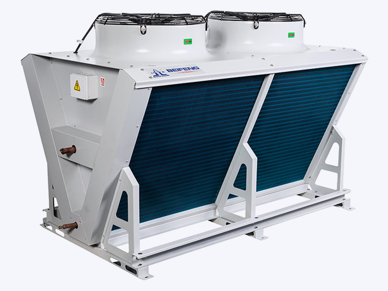
A clearance of at least one fan diameter from walls, screens and adjacent units is the usual requirement, with more allowed on the discharge side. Rooftop units facing the prevailing wind lose measurable capacity when hot discharge air is pushed back into the coil. Where space is tight, A-frame or V-shaped coils give more surface in the same footprint at the cost of height and a heavier service lift.
Fin spacing and fouling allowance
A coil at 2.1 mm fin spacing carries roughly 40% more surface than one at 4 mm on the same face. In a clean plant room that density is free capacity; beside a bakery, a sawmill or a coastal car park it is a maintenance liability. Wider fins at 4–7 mm surrender some nominal capacity but hold their airflow far longer between cleanings, which is normally the better trade.
Refrigerant Choice, Pressure Drop and Materials
Refrigerant sets the pressure envelope of the coil. R404A and R507 work at familiar pressures but carry a global warming potential above 3,900; R448A and R449A reduce that to around 1,400 with a small temperature glide that must be allowed for in selection. CO2 pushes transcritical pressures to 100–120 bar and demands thicker tubes and tighter testing. Ammonia performs strongly but requires open or semi-hermetic compressors and a machinery room that satisfies local codes.
Keep refrigerant-side pressure drop small — an equivalent saturation loss of 0.3–0.5 K is a sensible target. Smaller tubes cut charge and cost but raise velocity and pressure drop, so the two are balanced rather than optimised in isolation.
Materials deserve more attention than they usually receive. Copper tubes with aluminium fins are standard; copper fins or a tested coating such as e-coat are what keep a coil alive in coastal or industrial air. Microchannel coils cut charge substantially but are harder to clean and less forgiving of vibration.
Part-Load and Low Ambient Control
The design point is one hour of the year. For the remaining hours the condenser is oversized, and by late autumn it can be badly oversized. Without control, low ambient drives condensing pressure down until the expansion valve loses its differential and the evaporator starves.
Three approaches cover most sites. Fan cycling is cheap and effective down to roughly 0 °C, but it swings head pressure and stresses fan motors. Variable-speed fans hold steadier pressure and cut night-time noise. Floating head pressure control lets condensing temperature fall with ambient instead of holding it up artificially; below about −5 °C, most systems also need a correctly sized receiver and subcooling or flooded-charge control.
Sound follows airflow. Most of the noise from an air-cooled condenser is fan noise, so check the rated sound pressure level at the nearest neighbour's boundary rather than at one metre from the unit.
Success: pairing a matched coil, fan and control package at the selection stage usually removes the whole class of disputes about whether the shortfall came from the condenser, the compressor or the installation.
What to Verify Before Approving the Drawing
A condenser drawing becomes a contract the moment it is signed, and most disputes trace back to a parameter that was never written down. The checklist below covers the items that repeatedly cause problems on site.
- Heat rejection in kW at your design ambient, your altitude and a stated condensing temperature.
- Performance at 50% load, not only at the design point.
- Fan input power in kW at design and at part load.
- Sound pressure level in dB(A), with the measurement distance and free-field condition stated.
- Coil face area, number of rows, fin spacing, tube diameter, and tube and fin materials.
- Refrigerant type and total system charge.
- Corrosion class and the test method behind it, since salt-spray hours mean little without the standard named.
- Pressure test and leak test records. Helium leak detection on condensers and evaporators is a reasonable requirement to write into the order.
- Certification relevant to your market: CE and UL for export, ISO 9001 and ISO 14001 for management systems, and a pressure vessel licence where water-cooled equipment is also involved.
Manufacturing depth is worth confirming too. A supplier with two production sites and regional sales offices can absorb a schedule change; a trader with a catalogue cannot. Zhejiang Beifeng Refrigeration has manufactured refrigeration equipment since 1986 and exports to Europe, South-East Asia, the Middle East, North America and Africa, so altitude and high-ambient corrections appear routinely in its selection work. Where the coil, the fan and the control logic need to be resolved together, send the duty and site conditions to the engineering team before the drawing is frozen.
Design to the Worst Hour, Not the Average Year
Air-cooled condenser design parameters are not a checklist to be ticked; they are a set of trades. Every kelvin of approach costs surface area. Every metre of altitude costs mass flow. Every millimetre of fin spacing trades clean-air capacity for real-world resilience. Projects that age well are those where those trades were made explicitly, written into the data sheet and verified at commissioning against the conditions actually present on site.
If only one number survives the procurement process, make it the heat rejection capacity at the design ambient and altitude, because that is the figure the compressor will ask about on the hottest afternoon of the year.