 English
 عربى
عربى 简体中文
简体中文
Coil Selection
Air Cooled Condenser and Evaporator Coils: Choosing the Pair That Survives Real Weather and Real Frost
Two fin-and-tube coils sit in the same circuit but obey completely different rules. Get one wrong and the symptom appears somewhere else entirely: at the high-pressure switch, in the defrost timer, or on the electricity bill.
A 48 cubic metre frozen store in a coastal town tripped its high-pressure cut-out every July afternoon. The compressor was healthy, the charge was correct, and the door seals were new. The two real problems were coils: a condenser with tight 2.1 mm fin spacing that had collected salt, dust and pollen for eleven months, and an evaporator whose fins had been bridged by frost long enough to bend the drain pan.
That combination is common, and it is normally decided at the quotation stage rather than in the field. The working rule is short: size the air cooled condenser coil for the worst ambient afternoon of the year, and size the evaporator coil for the humidity and frost behaviour of the room it serves. Catalogue capacity tables are a starting point, not a specification.
The Two Coils Do Opposite Jobs
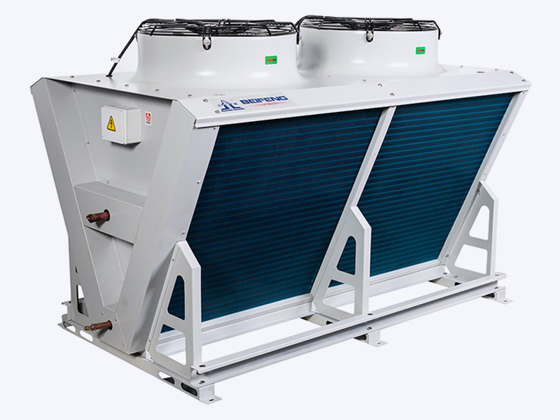
An air-cooled condenser coil receives superheated discharge gas from the compressor and rejects that heat to outdoor air, so the refrigerant leaves as liquid. An evaporator coil does the reverse inside the refrigerated space: it absorbs heat from the air, boils the refrigerant, and returns slightly superheated vapour to the compressor. Both are fin-and-tube heat exchangers, often listed side by side in the same catalogue, which is exactly why they get treated as interchangeable hardware.
| Parameter | Air-Cooled Condenser Coil | Evaporator Coil |
|---|---|---|
| Job in the circuit | Rejects heat to outdoor air | Absorbs heat from room air |
| Refrigerant state | Hot gas in, liquid out | Partly liquid in, superheated vapour out |
| Air side | Outdoor air, roughly 25 to 43 °C | Room air, roughly minus 25 to plus 10 °C |
| Design driver | Summer ambient temperature | Room temperature, load and humidity |
| Typical fin spacing | 1.8 to 3.0 mm, wider on dusty sites | 4 to 8 mm on freezer duty, 2 to 3 mm on medium temperature duty |
| Dominant failure | Fouling and high condensing pressure | Frost bridging and blocked drains |
Treat the table as a checklist rather than a description. If a quotation states fin spacing without stating the ambient design condition or the expected room humidity, the numbers cannot be verified later.
What Air Cooling Costs at the Condenser Coil
An air-cooled condenser works with whatever air the weather provides. On a well-matched coil the condensing temperature settles roughly 10 to 15 K above the ambient dry-bulb temperature, and every extra kelvin lifts compressor power by about 2 to 3 percent. Surface area, airflow and cleanliness therefore matter more than any single figure printed on a data sheet.
Selection usually begins with an approach temperature, meaning the gap between condensing temperature and design ambient. A target of 8 to 12 K suits most commercial condensing units. Going below roughly 8 K buys lower discharge pressure, but it demands considerably more coil face area and fan power, so the saving has to be weighed against capital cost.
Fin spacing on the condenser side is a fouling decision. Tight 1.8 to 2.5 mm spacing packs more surface into the same footprint; wider 2.5 to 3.5 mm spacing holds its capacity longer where cottonwood, cement dust or coastal salt is present. Placement matters just as much: leave at least one coil height of free space in front of the face, avoid corners that let hot discharge air recirculate, and keep the coil out of prevailing wind that pushes exhaust back across the fins.
The Evaporator Coil Is Where Humidity Sets the Rules
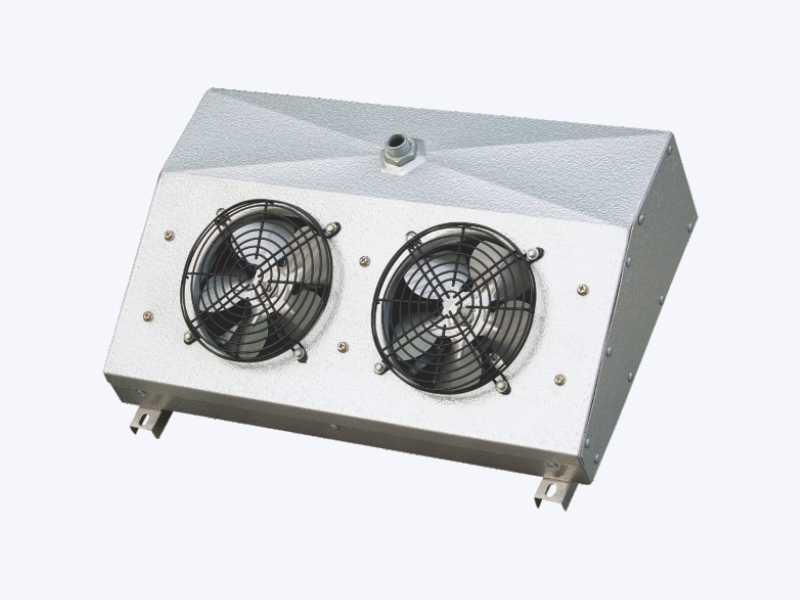
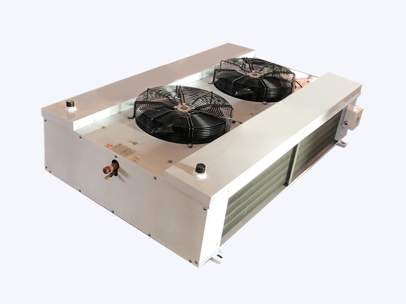
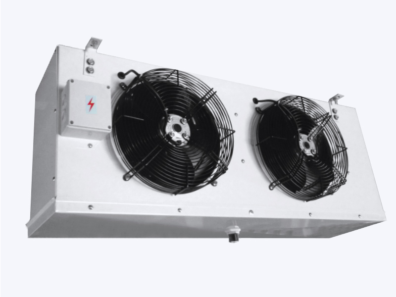
Inside the refrigerated space, the evaporator coil deals with two loads at once: sensible heat that lowers air temperature and latent heat that condenses moisture onto the fins. That is why fin spacing here is driven by frost, not by the desire for maximum surface.
Freezer coils generally run 4 to 8 mm spacing so frost can accumulate between defrost cycles without bridging the gap. Medium-temperature and chiller coils can use 2 to 3 mm because surface temperatures stay above freezing for most of the run time. Face velocity is usually held near 2 to 3 m/s to limit condensate carryover into the duct or the room.
The design temperature difference between room air and evaporating temperature is the second lever. Medium-temperature duty commonly uses 6 to 8 K, low-temperature duty 5 to 7 K. A very small difference gives gentle humidity removal but requires a large, expensive coil; a very large difference shrinks the coil and pulls moisture out quickly, at the cost of faster frost growth, longer defrost cycles and a heavier compressor load.
Defrost method, drain pan slope and drain line trapping should be chosen together with the coil. An efficient hot gas or electric defrost means very little if the melted water cannot leave the cabinet before the next pull-down.
Numbers Worth Writing Into the Specification
- Design ambient dry-bulb temperature for the condenser, including altitude and whether the site has a history of recirculation.
- Target condensing temperature and approach temperature, stated in kelvin.
- Room temperature, relative humidity and evaporating temperature, with the resulting temperature difference.
- Refrigerant type, required charge range, and the distributor or circuit arrangement.
- Expected subcooling of 3 to 5 K and superheat of 5 to 8 K at the coil outlet.
- Airflow in cubic metres per hour, plus the static pressure the fans must overcome.
- Defrost method, maximum cycle time, and the termination sensor position.
- A fouling allowance, typically 10 percent of surface area, for sites that cannot be cleaned monthly.
Written this way, a coil quotation becomes verifiable. Without these values, two suppliers can quote the same kilowatt rating and deliver coils that behave nothing alike in the same room.
Construction Details That Decide Service Life
Tube diameter, fin pattern, casing thickness and joint quality decide how long a coil holds its capacity. Copper tube with aluminium fins remains the mainstream choice for commercial refrigeration, with 3/8 inch, 1/2 inch and 5/8 inch tubes covering most duties. Louvered fins raise air-side heat transfer but collect lint faster; flat or corrugated fins tolerate dirty sites better. Anti-corrosion or hydrophilic coatings are worth specifying near the coast or in food plants that wash down equipment regularly.
Mechanical details deserve the same attention: a galvanized casing thick enough to resist fan vibration, staggered tube rows, a properly sized header, and brazed joints that survive transport. Leak integrity should be demonstrated rather than promised, which is where helium leak detection and a documented pressure-hold test earn their place in the order.
A coil is judged twice: once on the drawing, and once after three years of dust, salt air and defrost cycles. Only the second verdict stays with the customer.
Match the Coil to the Machine, Not to the Catalogue
A condenser coil must be matched to the compressor at the design point, not at nominal rating. An undersized condenser raises discharge pressure and shortens compressor life; an oversized one lowers discharge temperature and can hold excess liquid in the receiver, which then has to be managed by the charge and the expansion device. On the evaporator side, oversizing reduces the temperature difference but risks weak oil return and an unstable expansion valve, while undersizing cuts humidity removal and stretches pull-down time after defrost.
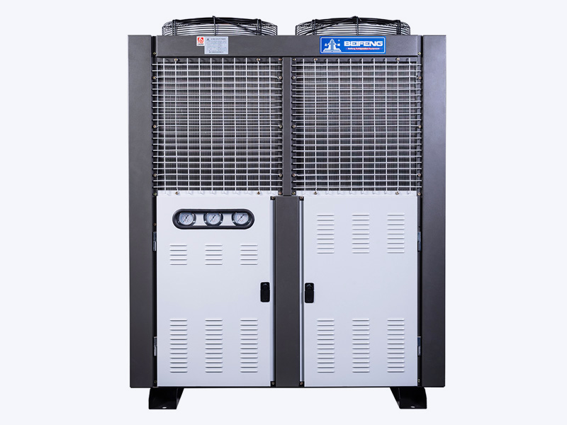
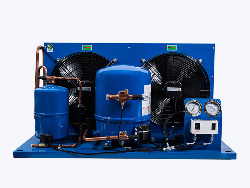
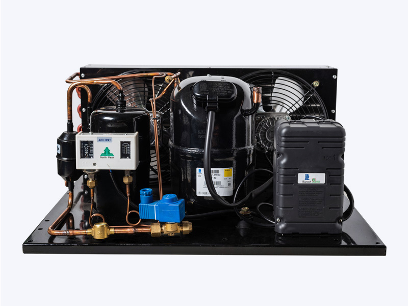
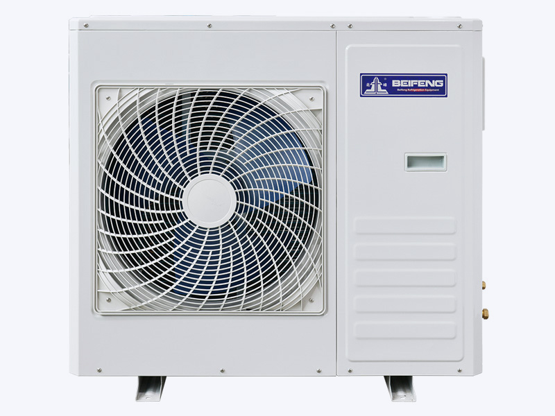
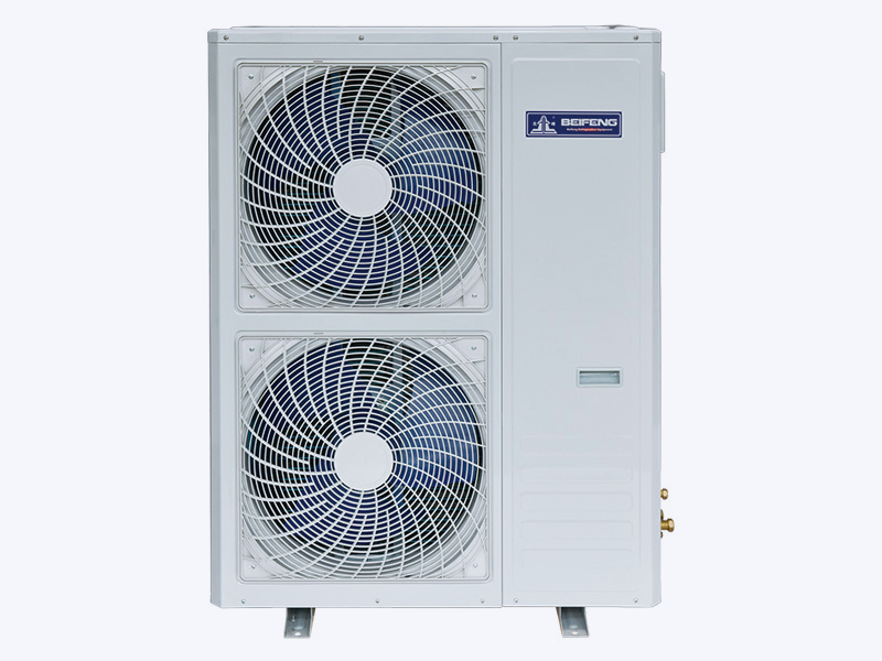
Packaged air-cooled condensing units remove much of that matching risk, because the coil, fan and compressor are tested as one assembly. Where coils are bought separately, ask for performance curves at your actual ambient and room conditions, and compare them against the compressor curve rather than against a single headline capacity figure. A short review of condenser selection criteria is a useful cross-check before the order is placed.
Field Patterns: What Fails First
- Condenser fins clogged with dust, pollen or grease, producing high discharge pressure that looks like a refrigerant fault.
- Hot air recirculating from one coil bank into the face of the next, common in walled courtyards and rooftop enclosures.
- Frost bridging on evaporator fins caused by fin spacing that is too tight for the room's moisture load.
- Condensate overflowing the pan because the drain line was trapped incorrectly or the pan lost its slope after installation.
- Copper tube corrosion under a coating that was damaged during transport or installation.
- Fan motor failure from continuous operation at high ambient, often on the unit that is hardest to reach.
Never pressure-test or leak-check a coil without confirming the casing and header ratings first. A coil that passes a workshop test can still fail on site if the isolation valves, relief devices and charging procedure are not planned together.
Practical maintenance that pays back: clean the condenser face every quarter in urban or dusty locations, check subcooling and superheat after every service visit, and record the ambient temperature alongside the reading so trends become visible over seasons.
What to Ask Before You Place the Order
Suppliers who manufacture heat exchangers in volume can usually answer these points in writing, and the answers separate a reliable coil from a low quotation.
- Which pressure test and leak detection methods are used, helium or nitrogen, and what acceptance limit applies.
- Which management system and product certifications are held, for example ISO 9001, ISO 14001, CE, UL and RoHS where export markets require them.
- Whether a production licence covers fin heat exchangers and evaporators, and whether pressure vessel permits apply to condenser assemblies.
- What documentation ships with the coil: performance curves, material certificates, test reports, piping and wiring diagrams, and spare parts lists for fans and motors.
- How the coil is packed for sea freight, since bent casings and crushed fins are the most common transport claims.
If the answers are vague, the risk transfers to the installation team, the service contractor and eventually the end user. It is far cheaper to clarify these details during the inquiry than to replace a coil in a working plant. You can also send the design conditions directly to the manufacturer and ask for a matched coil selection rather than a catalogue number.
Condenser coils and evaporator coils fail for different reasons, so they should be selected against different criteria. The condenser answers to the hottest afternoon of the year and to whatever the air carries, which makes approach temperature, airflow and fin spacing non-negotiable. The evaporator answers to humidity and frost, which makes fin spacing, temperature difference and defrost design the deciding factors. Get both right and the system runs at stable pressures, defrosts on schedule, and stays out of the maintenance queue.