 English
 عربى
 简体中文

Air-Cooled Condenser Design Specifications
What the rating sheet does not tell you about the unit on your roof
A food-processing plant in eastern China replaced its air-cooled condenser last summer. The contractor chose a unit with a larger face area than the original, assuming more surface meant more safety margin. Within two weeks, head pressure climbed past 18 bar every afternoon, the compressor tripped on its high-pressure safety, and the cold-room temperature drifted two degrees. The condenser was not undersized. It was mis-specified: dense fins that were right for a clean site had been bolted beside a fryer exhaust, and the coil fouled in days.
The design specification of an air-cooled condenser is not one rating number. It is a set of decisions about heat rejection, ambient temperature, fin geometry, airflow, materials, and installation clearance, and every decision must survive contact with the site where the unit runs.
Start with Heat Rejection and Design Ambient Temperature
Every air-cooled condenser design specification starts from two numbers. The first is total heat rejection: the sum of the refrigeration duty and the compressor power input, which for a semi-hermetic reciprocating system at medium-temperature conditions is roughly 1.15 to 1.35 times the evaporator load. The second is the design ambient temperature, because a condenser rated at 32°C ambient does not hold its condensing temperature at 40°C. As ambient rises, condensing temperature follows almost step for step, and every extra degree of condensing temperature adds roughly 1.5 to 2.5 percent to compressor power.
A practical example: a system designed for 45°C condensing in a 32°C ambient operates on a 13°C temperature difference (TD). On a 40°C afternoon, the condenser can only hold the same heat rejection by letting the condensing temperature rise, so the system settles near 53°C and the compressor draws roughly 15 percent more energy for the same duty.
| Application | Design ambient | Condensing temp. | Typical TD | Fin spacing |
|---|---|---|---|---|
| Commercial refrigeration | 32-35°C | 45-50°C | 10-15°C | 2.0-2.5 mm |
| Industrial process cooling | 38-40°C | 50-55°C | 12-18°C | 3.0-4.0 mm |
| Power / heavy process | 40-45°C | 55-65°C | 15-25°C | 4.0-6.0 mm |
Warning"Big enough" in rated capacity is not "big enough" on a real roof. Always ask for capacity at your actual design ambient, not at the standard rating condition, because every supplier publishes ratings at a fixed TD.
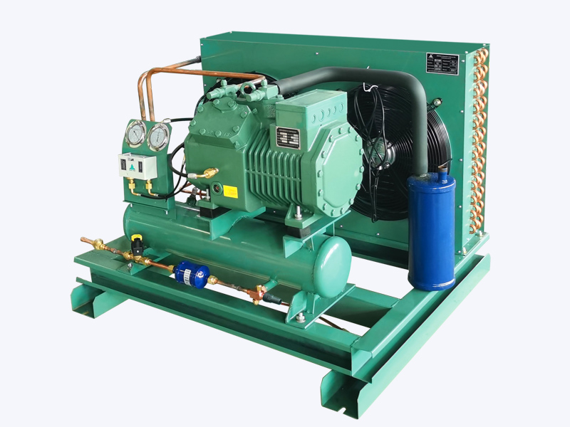
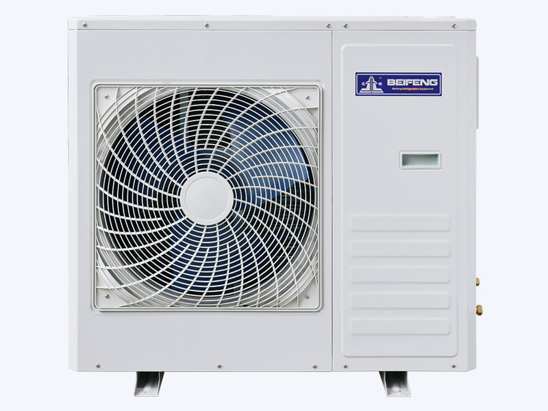
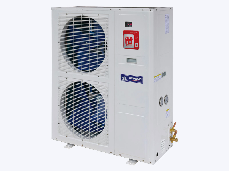
When the compressor and condenser are chosen together at the factory, the two numbers are locked into one specification. For retrofit projects, a packaged semi-hermetic air-cooled condensing unit is often the safer route, because the matched condenser, compressor, and controls have been validated as a set instead of guessed at separately.
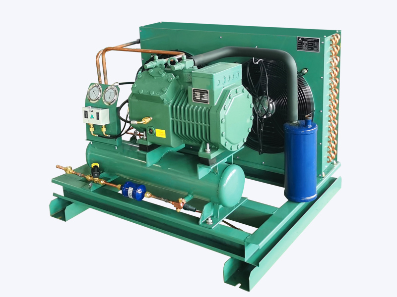 Semi-Hermetic Air-Cooled Condensing Unit for Reliable Commercial RefrigerationThis packaged unit matches condenser, compressor, and controls for retrofit projects. Its robust features suit cold storage and supermarket systems where dependable performance is key.View Product →
Fin Geometry: The Specification Most Likely to Fail
Fin density is usually the first line of a condenser datasheet, given in fins per inch or millimetres of spacing. Tighter spacing, such as 2.0 mm, packs more surface into the same face area and reduces fan power, but it also shortens the cleaning interval. Fin-and-tube coils with copper tubes and aluminium fins remain the workhorse of commercial refrigeration, while microchannel designs reduce refrigerant charge at the price of lower tolerance for fouling and aggressive cleaning.
Every manufacturer rates capacity at a stated TD. The moment the site TD is lower than the rating condition, the condenser must be physically larger, or the system must accept a higher condensing pressure.
- 2.0-2.5 mm spacing for clean roof sites, supermarkets, and light industrial environments.
- 3.0 mm for food processing, bakeries, and workshops with moderate dust or oil mist.
- 3.5-4.0 mm for textile mills, woodworking, and coastal installations with protective coil coating.
- 4.5 mm and wider for heavy fouling or for very high ambient process duty.
In supermarket duty, where a clean site makes dense fins acceptable, the operating strategy matters more than peak capacity. An inverter supermarket condensing unit holds head pressure stable without flooding refrigerant into the condenser, which reduces the average condensing temperature over the year.
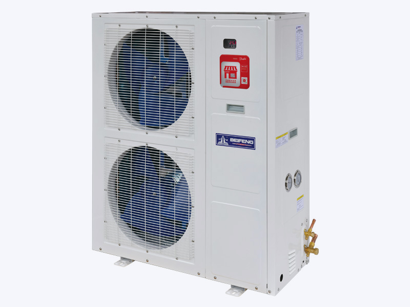 Inverter Condensing Unit for Supermarkets with Stepless Capacity ControlUsing Danfoss inverter scroll components, this unit adjusts capacity 30–100% to save about 30% annual operating cost. Ideal for cabinets and walk-in cold rooms.View Product →
Fan and Airflow: Where Performance Meets Installation
Face velocity is the governing airflow specification. Most fin-and-tube air-cooled condensers are designed for a face velocity between 2.0 and 3.5 m/s. Below that range, the air-side heat transfer coefficient drops sharply; above it, fan power rises with the square of velocity while heat transfer gains flatten. Fan selection must also respect noise limits, especially when the unit sits near occupied spaces.
InfoFor retrofits, measure the actual entering-air temperature at the coil face during the hottest hour of the year. A 5°C gap between published weather data and the coil inlet means the capacity table must be de-rated, no matter what the datasheet promises.
Recirculation is just as decisive. When discharge air from the top of a condenser is drawn back into the inlet by parapets, walls, or neighbouring units, entering air temperature rises and capacity falls silently. A clearance of 1.5 to 2 times the condenser height is the accepted minimum for rooftop rows.
For large industrial duties, the same airflow logic scales up, but the equipment form changes. A screw-type condensing unit packages the condenser, oil management, and capacity control in one assembly, so the air side and the refrigerating side are matched by the manufacturer rather than by the installer.
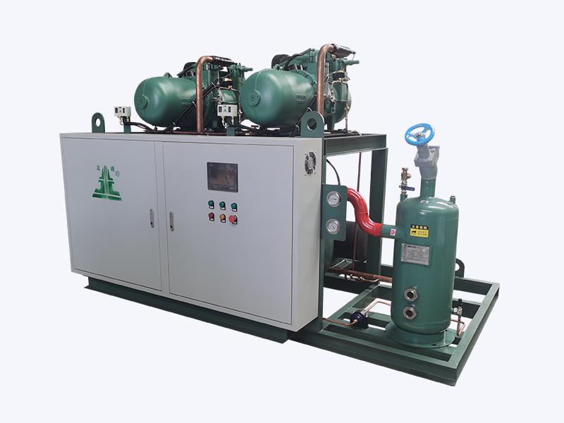 Screw-Type Condensing Unit for Industrial Refrigeration with Flexible ConfigurationsOffering single or paralleled setups with high, medium, and low-temp series, this unit provides multi-level energy adjustment and robust protection for demanding large-scale duties.View Product →
Coil Materials and Corrosion Protection
Aluminium fins on copper tubes form a galvanic couple. In a dry inland climate this is manageable, but in coastal or industrial atmospheres the fin edges corrode first, sometimes within two years. The material specification must therefore state fin grade, coating type, and tube wall thickness as one integrated choice, not as separate dropdown options.
DangerA painted cabinet is not corrosion protection for the coil. If the site is near salt water or in a coastal industrial zone, specify an enhanced fin coating and inspect the fin edges during the first six months of operation.
Confirm three values in writing: fin coating (epoxy or acrylic for salt exposure), tube wall thickness (0.35-0.5 mm for clean commercial, 0.8 mm or heavier for aggressive environments), and casing material (galvanized steel, with stainless hardware wherever condensate runs). The underlying coil construction and selection methods also determine how easily the coil can be cleaned when fouling eventually appears.
Verification: Testing and Compliance
A design specification is only as good as the verification behind it. Production testing should include pressure hold tests, helium leak detection on condenser and evaporator coils, and airflow or heat-transfer spot checks on the finished assembly. Vacuum helium leak detection in particular reveals porosity and joint defects that a simple nitrogen hold cannot find, which is why it is a standard step in modern coil test lines.
Compliance documents also matter. ISO 9001 covers the quality system, CE addresses European market entry, UL and RoHS serve North American and restricted-substance requirements, and a pressure vessel licence is required where the condenser falls under local boiler rules. These certificates do not change the physics of the coil, but they tell you that the manufacturer has actually tested the design.
Installation Constraints Are Part of the Specification
Placement limits the condenser design before a single tube is drawn. Units mounted near walls, under canopies, or inside fenced compounds need a fan static pressure adequate for ducting, baffles, or wind shielding, and a condenser specified for free-discharge rooftop duty will lose performance rapidly if it is boxed in later. Maintenance access decides whether a dense fin spacing is realistic, because a unit that cannot be reached for pressure-washing and coil inspection will fail at the fin density you selected.
Orientation against prevailing winds, distance to the evaporator, and the structural design of the support frame all feed back into the specification. When in doubt, give the manufacturer a measured site survey rather than a number from a weather app. For retrofit projects, our engineers review these conditions before recommending a unit; you can submit your site details for a design review before the purchase order is finalised.
The Specification That Matches the Site
The air cooled condenser design specification you actually need is not the unit with the largest face area, nor the one with the lowest first price. It is the condenser whose heat rejection matches your real ambient, whose fin geometry matches the real fouling environment, whose fan power fits the electrical and acoustic limits, and whose materials are chosen for the local corrosion risk.
SuccessWhen these parameters are fixed before purchase, the outcome is predictable: stable head pressure, fewer cleaning cycles, and a condenser that still rejects heat on the hottest afternoon of its service life.