 English
 عربى
 简体中文

Air-Cooled Heat Rejection
The Fan Is Not an Accessory — It Is Where the Condenser Actually Operates
Blade profile, tip clearance, impeller diameter and speed control decide whether an air cooled condenser holds its head pressure at 38 °C ambient, or quietly gives away capacity while the compressor covers the difference.
A 30 HP air cooled condensing unit on a supermarket roof in southern China reads 21 bar discharge on a July afternoon when the design figure is 17 bar. The coil is clean, the refrigerant charge has been verified twice, the unit is barely two years old. What changed is the air side: a replacement propeller turning at around 890 rpm behind a fine-mesh guard grille, blowing into roughly 40 cm of wall clearance that sends hot discharge air straight back into the coil inlet.
Fan design problems rarely look like failures. Nothing trips, nothing alarms — the system simply settles at a higher condensing temperature and pays for it every hour of the cooling season. The rule of thumb is worth keeping in mind throughout: every 1 K of excess condensing temperature costs roughly 2–3 % in compressor power, so a 4 K error is a permanent 10 % on the electricity bill.
The four fan variables that decide condensing temperature
Before blade counts, motor brands or guard styles, a condenser fan is only ever balancing four things. Put them in the right order and everything else becomes detail work.
Airflow measured at the coil face, not at the fan outlet
Fan catalogues quote free-air delivery. A two-row coil with 2.0 mm fin spacing, plus a guard grille, presents 30–60 Pa of resistance, and the impeller slides down its curve to a noticeably lower flow. Size the fan against the installed operating point and never against the free-air figure.
Diameter before speed
For the same airflow, a larger impeller turning slowly is quieter and usually draws less power. Commercial condensing units typically use 400–630 mm propellers; larger rooftop and industrial units move up to 800 mm and beyond, precisely so the motor can stay slow.
Blade geometry, including the parts nobody draws
Skew, camber, hub ratio and blade count set the noise spectrum and the stall margin. So does the gap between blade tip and venturi ring, which is a manufacturing tolerance as much as a design decision.
The drive and the control logic behind it
Fixed-speed with fan cycling, two-speed, or EC variable speed. This single choice decides part-load behaviour, and part-load is where most condensers spend most of their operating hours.
What good fan design numbers actually look like
Arguments about fan design go in circles quickly because everyone quotes a different figure of merit. The short list below is what we check when deciding whether a condensing unit's air side is under-designed, correctly sized, or being asked to do something the coil geometry cannot support.
| Design variable | Practical target | What it protects | Symptom when it is missed |
|---|---|---|---|
| Coil face velocity | 2.0–3.0 m/s at design ambient | Heat transfer without excessive air-side pressure drop | Condensing temperature drifts upward at full load |
| Fan swept area vs coil face | Roughly 55–75 % of the coil face | Even air distribution across the whole coil | Hot spots, uneven subcooling, one-sided fouling |
| Tip clearance | 5–10 mm, or no more than 1 % of diameter | Static efficiency and tonal noise | Whistling tone and 3–6 % higher power draw |
| Blade count and skew | 5–7 blades, skewed or unevenly spaced | Broadband rather than tonal sound | Complaint-level noise at blade-passing frequency |
| Motor and control range | EC or two-speed, minimum speed ≥ 30 % | Part-load efficiency and pressure stability | Fan hunting, pressure swings, low-ambient icing |
| Fan spacing and wall clearance | ≥ 0.5 × diameter between fans, ≥ 1 × diameter from walls | Discharge air that leaves instead of returning | Head pressure climbs in hot weather, not in spring |
Diameter, speed and the fan laws that punish small blades
Fan laws are simple and unforgiving. Airflow scales with speed, static pressure with the square of speed, shaft power with the cube, and sound rises steeply — on the order of 12–15 dB for a doubling of rotational speed. The consequence is blunt: if a unit is short of airflow, raising the speed of a small impeller is the most expensive correction available, in power, in noise and in bearing life.
Impeller diameter buys airflow at lower rotational speed. A 630 mm propeller at 700 rpm and a 450 mm propeller at roughly 1,370 rpm can move similar air, but the smaller one will usually be louder, draw more power at the same duty, and lose more performance once the coil begins to foul. On noise-sensitive sites, tip speed is the number to watch: keeping blade tips below about 60–65 m/s avoids the sharp rise in blade-passing tone that neighbours notice first, long before any measured sound level becomes a formal complaint.
Tip clearance, blade skew and the noise people actually notice
Tip clearance is the quiet killer of fan performance. A 2 mm increase on a 500 mm impeller looks like nothing on a drawing, yet it can cost several percent of static efficiency and produce a narrow-band whistle that carries into the next building. Practical limits are worth writing into any specification: clearance no more than about 1 % of impeller diameter, hub ratio in the 0.3–0.4 range, and either a skewed trailing edge or uneven blade spacing to spread tonal energy into broadband sound. Published tests using vortex-shedding control strips and asymmetric blade profiles have reported 1–2 dB reductions — modest numbers that decide the outcome when a site sits 3 dB above its permit.
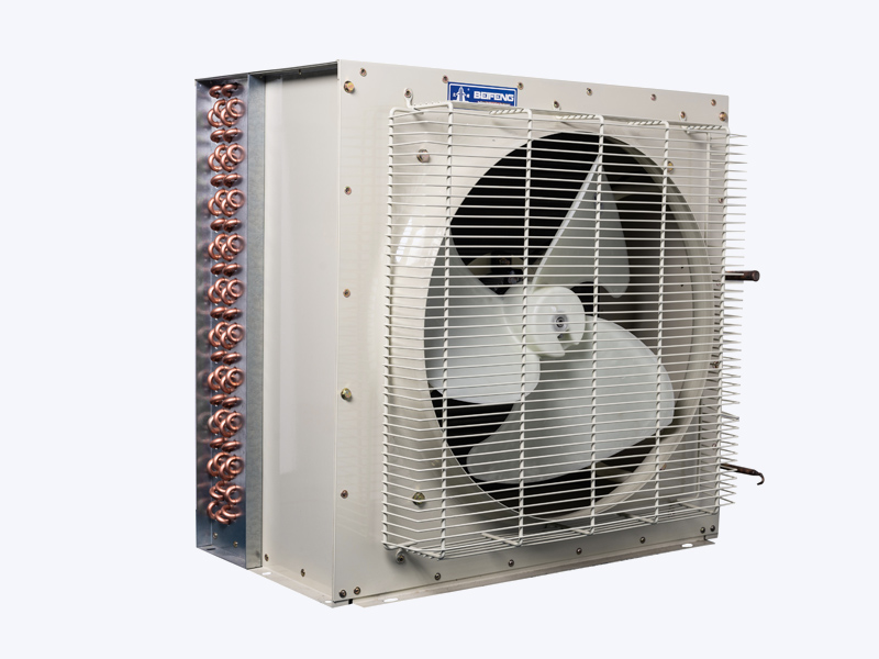
The guard grille belongs to the fan as well. A fine protective mesh can add 10–20 Pa of resistance and distort inflow; a coarser wire guard with 20–25 mm pitch usually costs less performance for the same safety function.
A fan that is 3 dB louder carries twice the sound power. Slowing the same fan by 15 % cuts its power draw by nearly 40 % and its airflow by 15 %. Which of those two numbers matters more is a site decision, not a catalogue decision.
For the wider picture of how blade and airflow choices interact with coil behaviour, our note on fan design and airflow characteristics in air cooled condensers follows the same variables at system level.
Matching fan control to the unit and to the application
An installed fan only performs as well as its control strategy allows. A retail condenser running an inverter-driven medium-temperature circuit varies fan speed continuously and holds condensing pressure inside a narrow band while store load swings through the afternoon; a fixed-speed unit cycling three fans in steps does fine at 32 °C ambient and struggles at 2 °C, where the coil over-condenses, liquid subcooling collapses and the expansion valve loses authority.
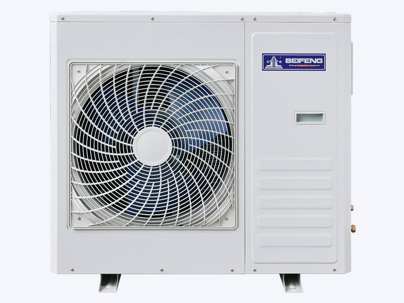
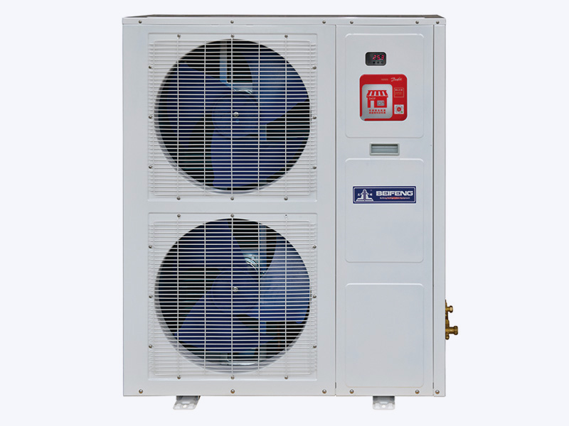
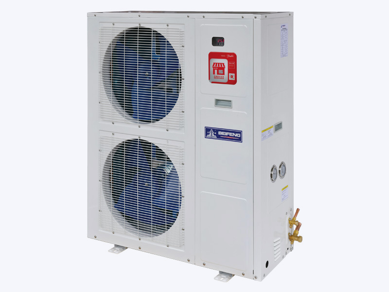 Supermarket and C-Store Medium-Temp Inverter Condensing UnitMedium-temperature inverter condensing unit for convenience stores, with adjustable-speed fans and Danfoss controls suited to varying store loads.View Product →
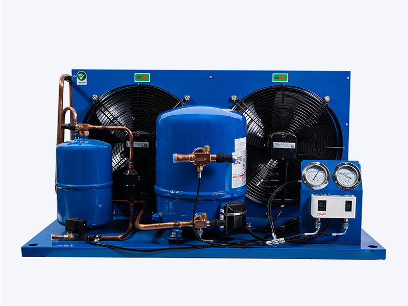
On semi-hermetic air cooled condensing units, the fan package is normally sized for a declared ambient with a small margin, and the design question becomes where that margin sits — extra coil face area is quiet, extra fan speed is not. Reviewing the fan curve against the actual coil pressure drop, rather than against a nominal airflow, is the step that most often exposes a mismatch before the unit leaves the factory.
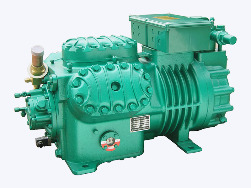
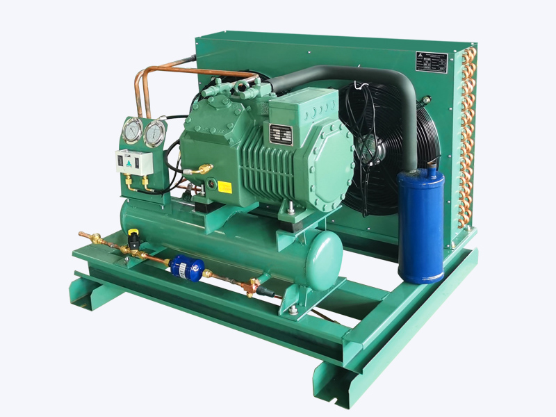 Semi-Hermetic Air-Cooled Condensing Unit, 3HP–25HPAir-cooled semi-hermetic condensing unit covering 3HP–25HP and multiple refrigerants, relevant when checking fan performance against coil pressure drop.View Product →
For larger duties, screw-type condensing units typically run two or three fans across a divided coil, which allows partial coil operation at low ambient and staged airflow without stopping the whole condenser. In that arrangement, fan spacing and the sequence in which fans start matter as much as blade design, because a badly sequenced set of fans can pull discharge air across a neighbouring coil section and cancel the benefit of the extra surface.
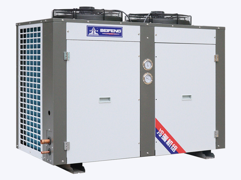
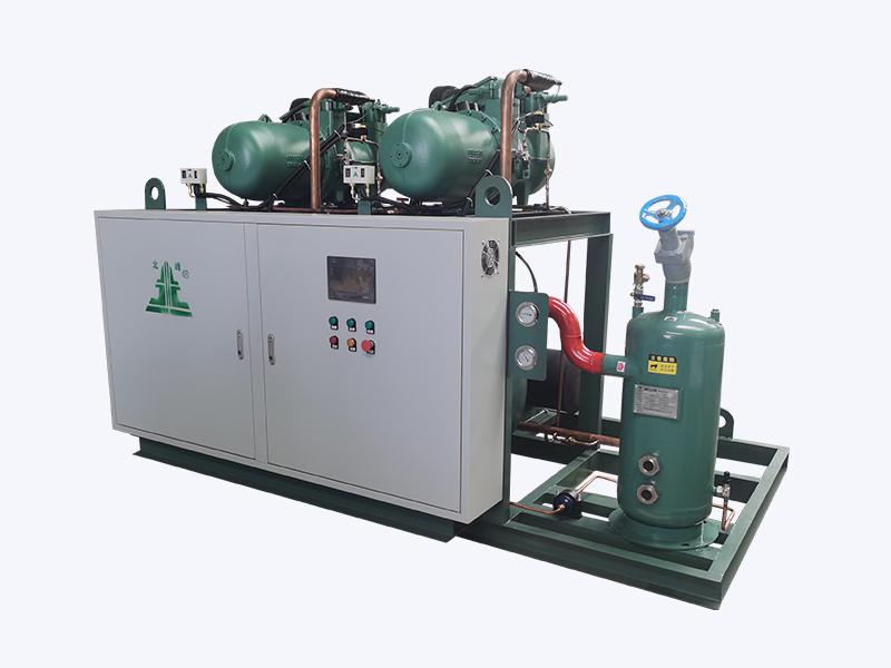 Screw-Type Condensing Unit for High, Medium, and Low TemperatureScrew-type condensing unit in single and paralleled configurations for multiple refrigeration systems, suited to larger duties with staged fan operation.View Product →
Commissioning checks that expose a fan design problem
Most air-side faults can be found in a single visit if the checks are done in order, at design or near-design ambient, with the unit at stable load.
- Confirm rotation direction and blade pitch against the nameplate — a reversed three-phase fan still moves air, just far less of it.
- Measure motor current and compare it with the rated figure; a fan drawing close to nameplate rating is usually fighting a restricted coil or a badly fitted venturi.
- Check approach temperature: condensing temperature minus ambient should sit in the 8–12 K band on a clean coil at design airflow.
- Sweep a smoke pencil around the coil inlet and the top of the unit to find recirculation, the most common rooftop fault.
- Log vibration velocity and bearing temperature after thirty minutes of running; anything above about 4.5 mm/s RMS justifies a look at balance and tip clearance.
- Verify control staging — minimum speed, dead band and the number of fans permitted at low ambient — against the sequence the unit was designed for.
What to write into a fan specification
Four lines separate a useful fan specification from a vague one: required airflow at the real coil pressure drop rather than free air; permitted sound pressure at a stated distance and octave band; the control range, expressed as a minimum speed percentage; and the ambient temperature at which full capacity must still be delivered. Add the corrosion class — coastal and food-processing sites need different motor and blade finishes than a dry inland plant room — and the maintenance access requirement, because a fan that cannot be removed without cutting pipework will not be serviced.
Info A fan quoted at 9,000 m³/h free air may deliver only around 6,500 m³/h once the coil, grille and louvre are in place. Always specify the installed operating point.
Warning Below roughly 5 °C ambient, step-cycling fans on a fixed-speed condenser can drop head pressure faster than the expansion valve responds, which shows up as liquid-line flashing and erratic superheat.
Good air cooled condenser fan design is rarely about the most advanced impeller on the market. It is about matching an impeller to the real coil resistance, keeping tip clearance honest, choosing a diameter that lets the motor run slowly, and letting the control strategy use that range across the whole year. Get those four right and the condenser holds its design condensing temperature through August, the compressor draws what the datasheet promised, and nobody in the building next door files a noise complaint.
If you are specifying a condensing unit or replacing a fan package on an existing coil, our engineering team can check the installed operating point against your ambient conditions and load profile — contact us with the coil drawing and the site details.