 English
 عربى
عربى 简体中文
简体中文
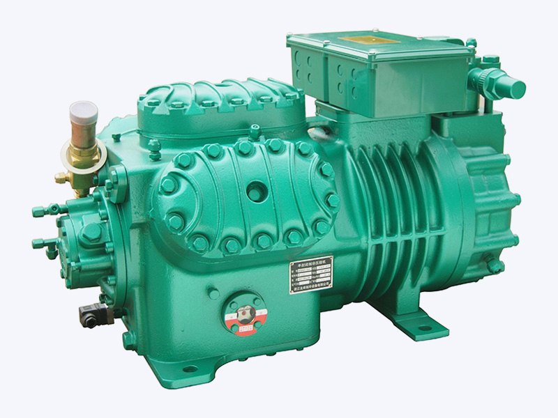
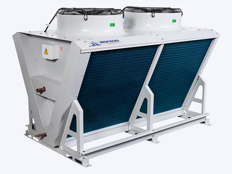
The refrigeration system is only as dependable as its rejected heat path. On paper, an air-cooled condenser looks simple: a finned coil and a fan. In practice, the design of that coil and fan decides discharge pressure, compressor power draw, summer capacity, and service intervals. The conclusion engineers and contractors should take from the design exercise is straightforward. When an air-cooled condenser is correctly specified for the site, the rest of the system behaves predictably. When it is not, every other component pays the price.
This article covers the design fundamentals that matter most in refrigeration applications: the heat rejection zones inside the condenser, the selection parameters that control performance, the trade-offs against water-cooled alternatives, and the practical steps for matching a condenser to a compressor.
What an Air-Cooled Condenser Must Actually Do
In a vapor-compression refrigeration cycle, the condenser receives hot, high-pressure refrigerant vapor from the compressor discharge and converts it to liquid that can expand and absorb heat at the evaporator. The total heat the condenser rejects equals the evaporator load plus the compressor work input, so a useful rule of thumb is that the required heat rejection runs 20 to 40 percent higher than the rated cooling capacity, depending on operating conditions and compressor efficiency.
The refrigerant passes through three zones inside the coil:
| Zone | Phase change | Typical share of heat rejection | Design consideration |
|---|---|---|---|
| Desuperheating | Vapor cools from discharge temperature to saturation | 10 to 15% | Reduces entering gas temperature; helps protect fins near the inlet |
| Condensing | Vapor changes to liquid at nearly constant pressure and temperature | 75 to 80% | Dominates coil area; governed by fin surface and airflow |
| Subcooling | Liquid cools below saturation temperature | 5 to 10% | Improves expansion valve performance and prevents flash gas |
Because most of the heat is removed during condensation, the coil is sized primarily on condensing duty. Subcooling is often treated as a bonus achieved in the last coil rows, but in low-ambient climates it can become large enough to require pressure control and careful receiver management.
The Design Parameters That Decide Performance
Experienced engineers start with four numbers: design ambient temperature, condensing temperature difference, fin spacing, and face velocity. Everything else is detail on top of those.
Design Ambient Temperature and Condensing Temperature Difference
The condensing temperature is chosen as the design ambient dry-bulb temperature plus a difference (TD) of roughly 10 to 15 K. For example, a site with a 35°C summer design temperature leads to a 45 to 50°C condensing temperature. A smaller TD requires a larger, more expensive coil; a larger TD reduces coil cost but increases compressor power consumption because of the higher pressure ratio. The life-cycle cost optimum usually sits at a TD of about 8 to 12 K when energy prices are moderate.
Fin Spacing, Rows, and Face Velocity
- Fin spacing: 3 to 4 mm suits clean environments; 5 to 6 mm is safer for dusty industrial rooms or outdoor areas near roads and agriculture.
- Rows: three or four rows balance heat transfer against airside pressure drop. Six-row coils may condense more per square meter of face area, but they need stronger fans and collect dirt faster.
- Face velocity: roughly 2 to 3 m/s over the coil face works well for most refrigeration condensers. Too low, and heat transfer drops; too high, and noise, fan power, and carryover of condensate or oil mist increase.
Fin and Tube Materials
Aluminum fins on copper tubes with internal grooves are the standard construction for refrigeration duty. The internal fin pattern increases the refrigerant-side surface area and improves heat transfer without enlarging the coil. For coastal sites or environments with salt air or aggressive chemicals, request a protective coating on the fins and consider epoxy-coated coils, Teflon-coated aluminum, or stainless steel fasteners. The modest first-cost increase is cheap compared with premature coil failure.
The fin pattern itself also matters. Wavy or louvered fins improve airside heat transfer but collect dust more readily than flat fins. In a maintenance-friendly design, cleanable fin spacing and a coil that can be hosed down without damaging the fan motor are worth specifying.
Air-Cooled or Water-Cooled: Choosing the Condenser Concept
The air-cooled design wins when water is scarce, expensive, or poorly treated. It eliminates cooling towers, water pumps, chemical treatment, and the risk of freezing, and it can sit outdoors with only an electrical connection. The price is that condensing temperature follows ambient conditions: a system with an air-cooled condenser commonly operates 10 to 25 K above the outdoor temperature, which increases compressor work on hot afternoons.
Water-cooled shell-and-tube condensers operate closer to the wet-bulb temperature and hold a more stable head pressure. They make sense for large industrial loads, sites with reliable water quality, and indoor installations where the condenser heat would be difficult to reject. However, the total owning cost of the water circuit, including pumps, tower, water treatment, and blowdown, often exceeds the compressor-side energy saving unless the system is large or runs year-round at high load.
The practical recommendation: choose air-cooled for most commercial refrigeration systems up to several hundred kilowatts, unless the summer ambient is extreme, the site has a heat recovery need, or water is available with minimal treatment. Choose water-cooled when condensing temperature stability and large heat rejection rates dominate the design.
Refrigerant Selection and Component Requirements
Refrigerant choice changes the mechanical design of the condenser. Systems using high-pressure refrigerants such as R-410A require a condenser designed for a significantly higher maximum working pressure than R-134a or R-404A designs. Coil wall thickness, header strength, and braze joints all need to be verified against the refrigerant pressure rating and the applicable safety standard. With mildly flammable refrigerants such as R-290 or R-32, additional constraints on refrigerant charge and fan motor electrical classification appear.
Component-level details also matter:
- Fan motors: use thermally protected motors rated for inverter drive if the design includes variable-speed fan control.
- Receivers: size the receiver to hold the full system charge during pump-down and low-ambient operation.
- Service valves: generously sized access ports and isolation valves shorten service time and reduce the chance of refrigerant loss.
- Pressure control: fan cycling or condenser flooding prevents refrigerant migration and unstable operation in cold weather.
A condenser that is well matched to the compressor and its refrigerant avoids the most common field complaints: high discharge pressure in summer, liquid line flash gas, and excessive cycling in winter.
Installation and Airflow: Design Work That Happens on Site
The best-designed condenser can underperform if it is placed poorly. Keep the inlet and discharge clear: position the condenser away from building walls, parapets, or other units that could cause hot air recirculation. A minimum clearance of one fan diameter on the inlet and two to three meters of unobstructed discharge above the unit is a practical starting point.
Orientation also affects performance. Facing the inlet away from prevailing summer winds reduces recirculation; placing the unit in shade, or providing a simple roof screen, lowers the entering air temperature by a few degrees and improves capacity. In areas with fine dust, pollen, or cottonwood, a filter or scheduled coil cleaning is more effective than designing around a future obstruction.
Seasonal operation deserves its own attention. In cold climates, head pressure must be maintained above the minimum required for the expansion valve to work. Options include cycling fans on pressure switches, using a variable-speed fan drive, or fitting a condenser flooding regulator. These controls are part of the condenser design, not an afterthought.
Sizing and Matching in Practice
The conventional design sequence is straightforward: determine the evaporator load, add compressor heat to get required heat rejection, pick a design ambient temperature, choose a TD, and then select a coil with the necessary face area and fan airflow. For an initial estimate, many designers use about 130 percent of the net refrigeration capacity as the condenser duty at standard conditions, then verify with a coil selection program.
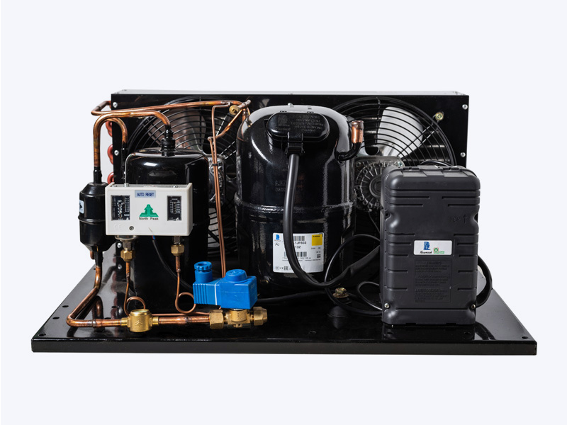
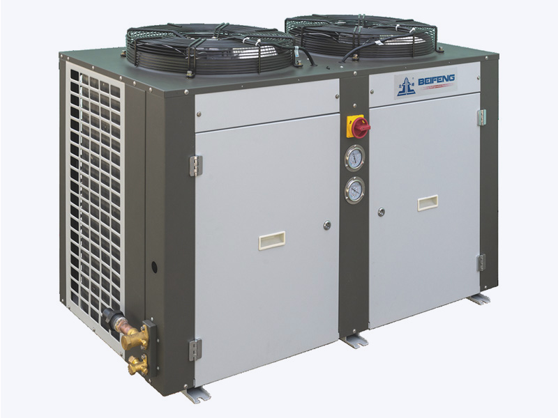
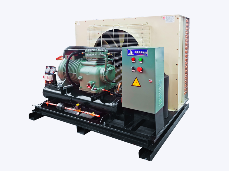
Yet the most reliable results come from factory-matched components. When we assemble a semi-hermetic compressor air-cooled condensing unit, the condenser coil, fan, receiver, and refrigerant charge are selected as one package, so the installer does not have to reconcile separate component data sheets. This removes a whole category of commissioning errors such as undersized receivers or fan airflow mismatches.
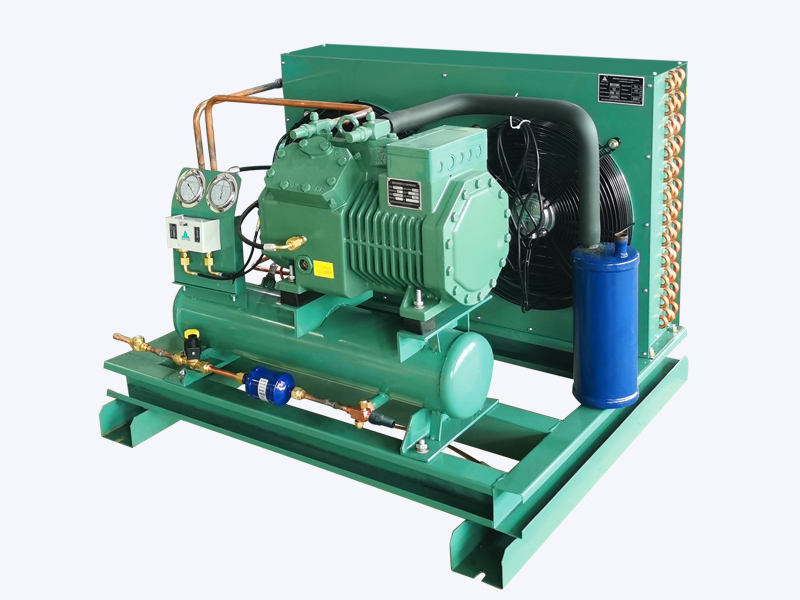 Wholesale Semi-Hermetic Compressor Air-Cooled Condensing Unit(3HP-25HP) Factory,Zhejiang Beifeng Refrigeration Equipment Co., Ltd is China wholesale Semi-Hermetic Compressor Air-Cooled Condensing Unit(3HP-25HP) factor...View Product →
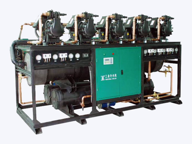
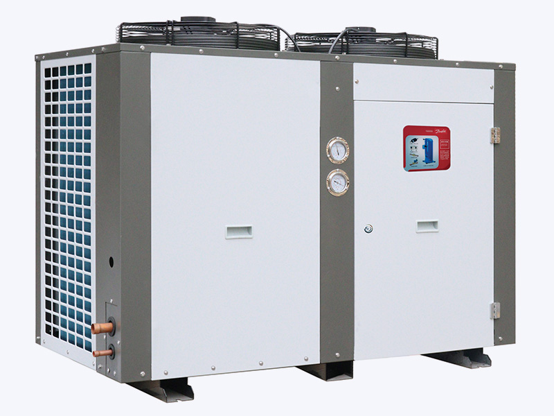
For larger cold storage or process refrigeration demands, a screw-type condensing unit brings the same matching advantage at higher capacities, where an incorrectly sized condenser would quickly show up in oil temperature and discharge pressure problems.
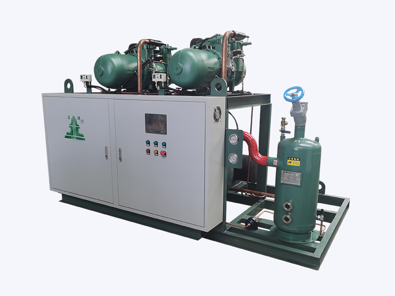 Wholesale Screw-Type Condensing Unit Factory, Company - Zhejiang Beifeng RefrigeZhejiang Beifeng Refrigeration Equipment Co., Ltd is China wholesale Screw-Type Condensing Unit factory and company, details:View Product →
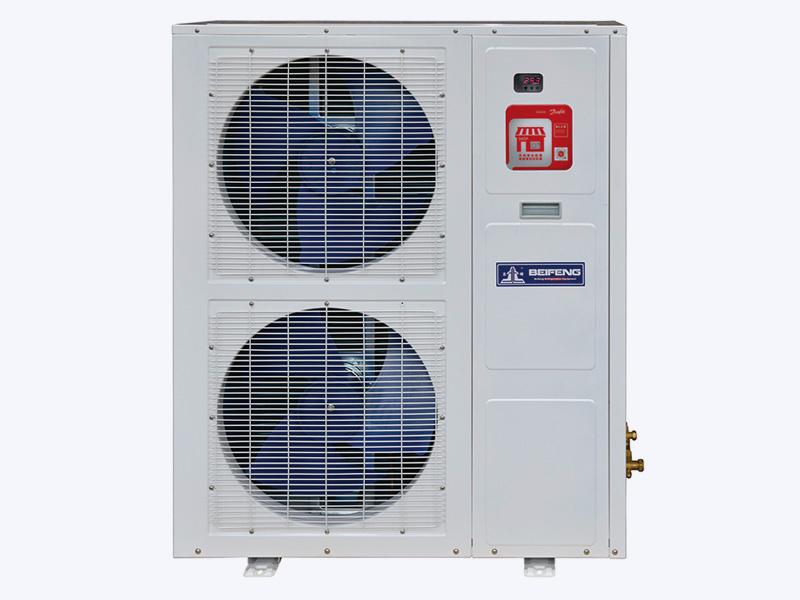
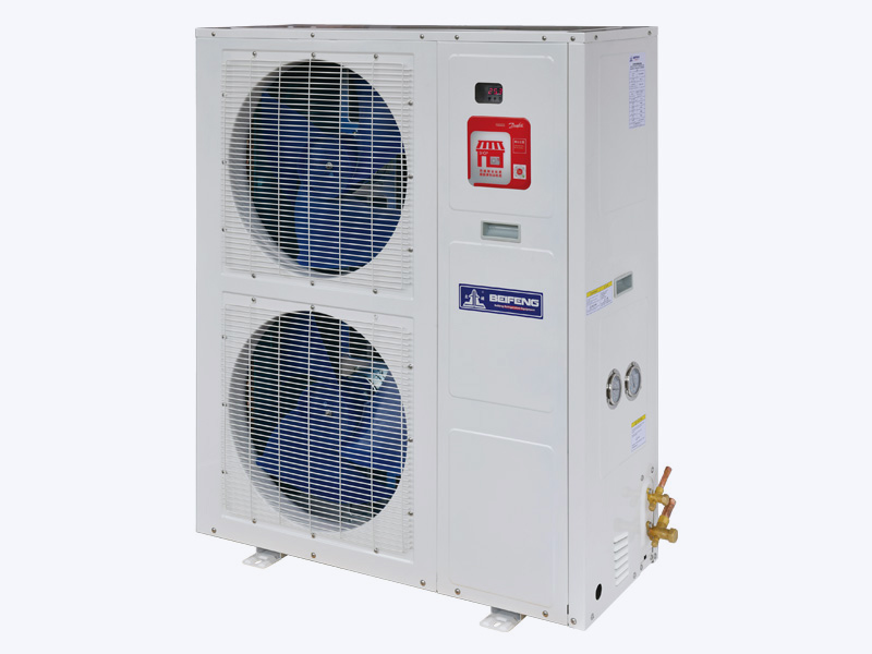
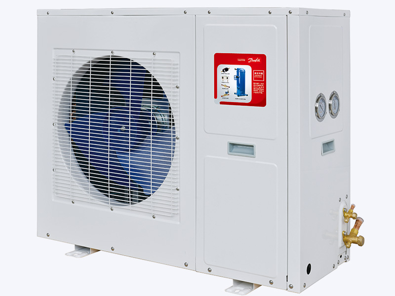
Retail refrigeration has its own pattern: frequent door openings, defrost cycles, and a wide range of ambient conditions. A supermarket medium-temperature inverter condensing unit addresses this with an inverter-driven compressor and matched condenser fan control, maintaining stable case temperatures at part load instead of cycling on and off.
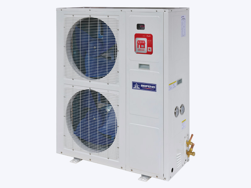 Wholesale Supermarket and C-store Medium Temp Inverter Condensing Unit Factory, Zhejiang Beifeng Refrigeration Equipment Co., Ltd is China wholesale Supermarket and C-store Medium Temp Inverter Condensing Unit factory...View Product →
Air-cooled condenser design is not a one-line calculation. Ambient data, fin geometry, airflow, refrigerant, and installation conditions all interact, and the consequences of a wrong choice appear over the operating life of the plant in higher energy bills, lost cooling capacity, and shortened compressor life. A concise understanding of the heat rejection zones and the key selection parameters already improves most design conversations. Then the decision comes down to matching the right components for the specific application. For site-specific cases, especially coastal exposure or extreme outdoor temperatures, it is worth having the coil configuration checked by the manufacturer. You can discuss the condenser design directly with our engineers or read about how an air-cooled condenser fits into the refrigeration cycle.